GRE (Generic Routing Encapsulation, full form: Generic Routing Encapsulation) is the simplest tunnel protocol in the network engineer's toolkit. You take any kind of network packet, wrap it inside an IP packet, and send it across an IP network as if you had a direct cable between the two endpoints. That is GRE in one sentence. RFC 2784 (with RFC 2890 adding key and sequence-number extensions) defines the format, Cisco invented it in the early 1990s, and three decades later it still underpins more enterprise overlays than any other tunnel technology because it is everywhere, it is well-understood, and it does exactly one thing well.
This is the cluster overview for the full PingLabz GRE series: how GRE encapsulation works, the packet format, configuration on Cisco IOS XE, routing protocols over GRE, keepalives, the MTU and fragmentation problem, GRE over IPsec, multipoint GRE / DMVPN, and troubleshooting. We will walk through the basics, then the parts of GRE that catch engineers out in production, then the operational realities. If you are configuring your first GRE tunnel, designing a hub-and-spoke overlay, or chasing a recursive-routing flap at 2 AM, start here.
What GRE Solves
GRE was built to carry network protocols that the underlying IP network does not natively understand. In the early 1990s that meant tunneling IPX, AppleTalk, and DECnet across an IP backbone. In 2026 the use cases are different but the core value is the same: GRE lets you treat an IP path between two routers as a virtual point-to-point link.
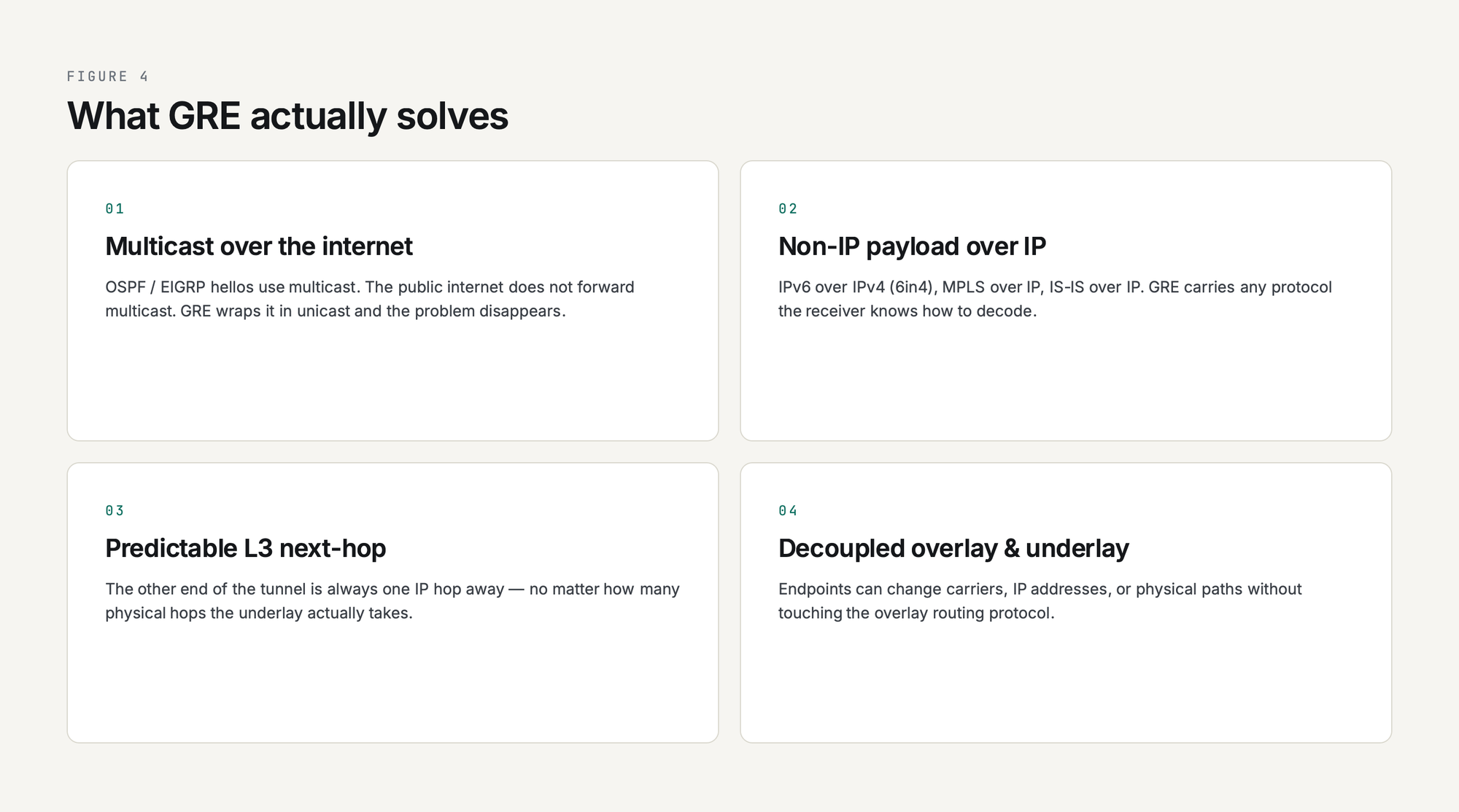
That virtual link gives you four things you cannot easily get from plain IP routing:
- Multicast over an internet path. OSPF and EIGRP rely on multicast hellos, and the public internet does not forward multicast. Wrap them in GRE and the multicast becomes a unicast IP packet the internet is happy to deliver.
- Non-IP payload over IP. IPv6 over IPv4 (6in4), MPLS over IP backbones, IS-IS over IP - GRE carries any protocol the receiver knows how to decode.
- A predictable Layer 3 next-hop. The other end of the tunnel is always one IP hop away no matter how many physical hops the underlay takes, which simplifies recursive routes, traffic engineering, and policy-based routing.
- Decoupled overlay from underlay. Tunnel endpoints can change carriers, IP addresses, or physical paths without touching the overlay routing protocol. GRE is the duct tape of network engineering, and it never wears out.
What GRE deliberately does not do is encrypt. There is no authentication, no confidentiality, no integrity protection in the GRE header. If you put GRE on the public internet, anyone who can capture the packets can read them. That is why production deployments almost always pair GRE with IPsec, which is the subject of GRE over IPsec: When and How to Combine Them.
How GRE Encapsulation Works (the 10,000-Foot View)
A GRE tunnel is just two routers that have agreed to wrap traffic for each other. There are no sessions, no handshakes, no negotiation. Each router has a tunnel interface configured with a tunnel source (the local underlay IP), a tunnel destination (the remote underlay IP), and a tunnel mode (almost always gre ip for plain GRE over IPv4). Anything routed into that tunnel interface gets encapsulated and sent to the destination.
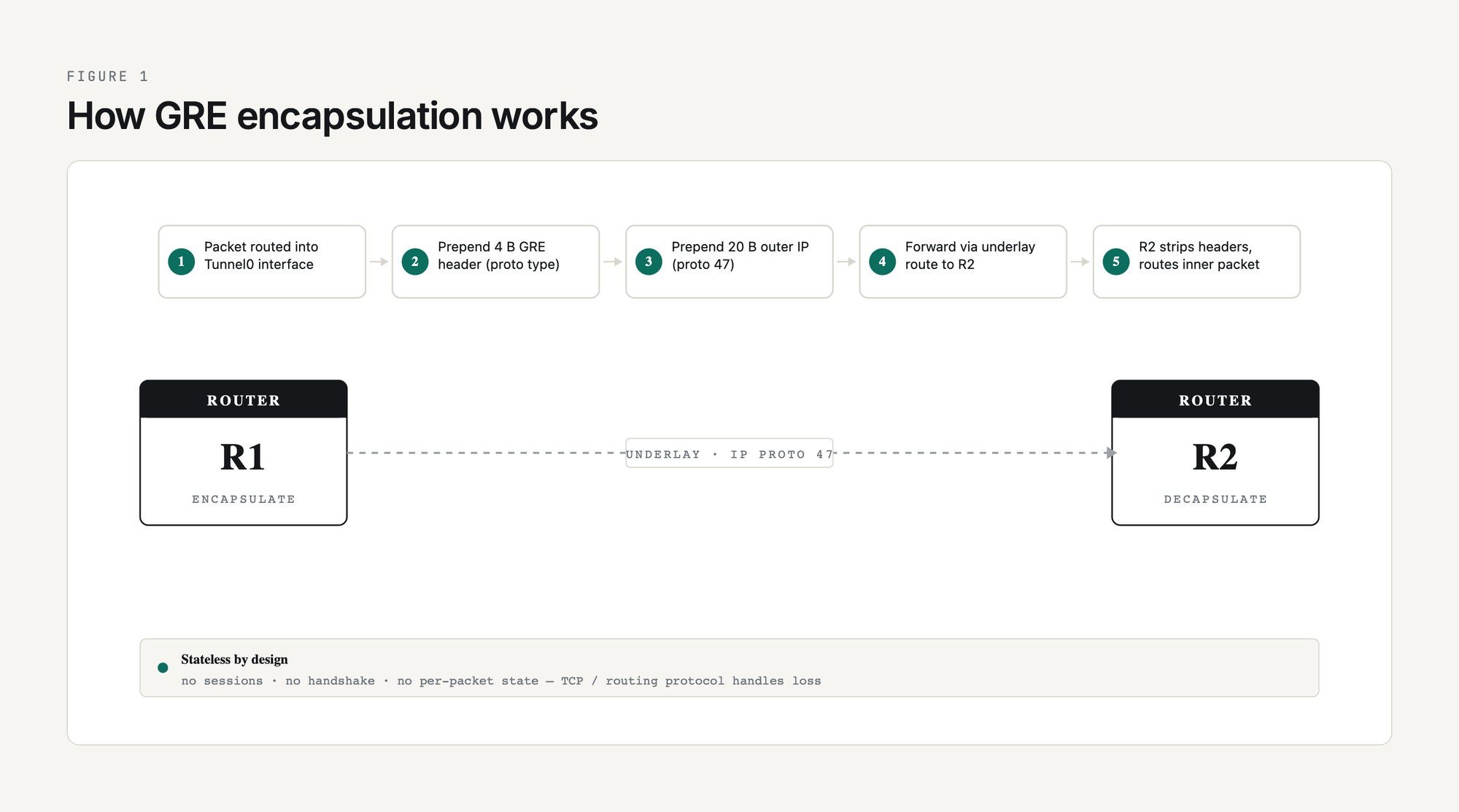
The encapsulation steps in order:
- A packet is routed into the tunnel interface by the IP routing table. The tunnel interface looks like any other interface to the routing process.
- The router prepends a GRE header (4 bytes minimum, more if optional fields are enabled) describing the protocol type of the inner packet.
- The router prepends an outer IP header. The outer source is the tunnel source IP, the outer destination is the tunnel destination IP, and the protocol field is set to 47 (the IANA-assigned GRE protocol number).
- The packet is forwarded out the underlay interface that the routing table says reaches the tunnel destination. From the underlay's perspective it is a plain IP unicast packet bound for some destination on the public internet.
- The remote router receives the packet, sees protocol 47, strips the outer IP and GRE headers, and routes the inner packet according to its own routing table.
That is it. There is no per-packet state on either end. If a packet is dropped, GRE does not know and does not care; the inner protocol (TCP, the routing protocol, whatever) handles loss recovery. This statelessness is GRE's strength (no fancy failure modes) and its weakness (no native liveness check, which is why GRE keepalives were added later).
GRE Packet Format
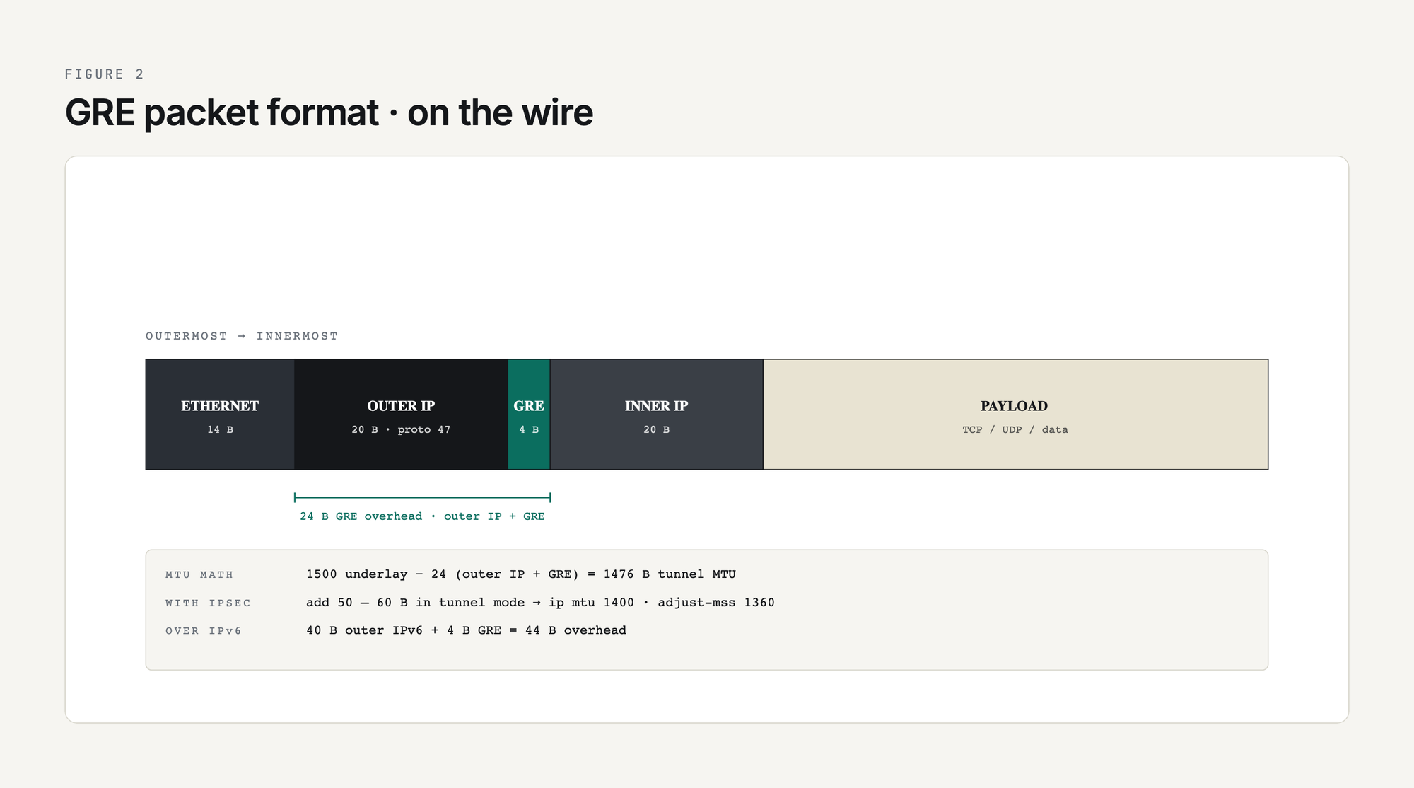
The wire format of a GRE-encapsulated packet, from outermost to innermost:
Total overhead added per packet is 24 bytes for plain GRE over IPv4 (20-byte outer IPv4 plus 4-byte GRE). That is the reason the canonical Cisco MTU recommendation for a 1500-byte underlay is 1476 bytes inside the tunnel. Add IPsec encryption on top of GRE and you lose another 50-60 bytes depending on the cipher and mode, which is why MTU-and-MSS becomes its own deep dive at GRE MTU and Fragmentation: Fixing Tunnel Packet Loss.
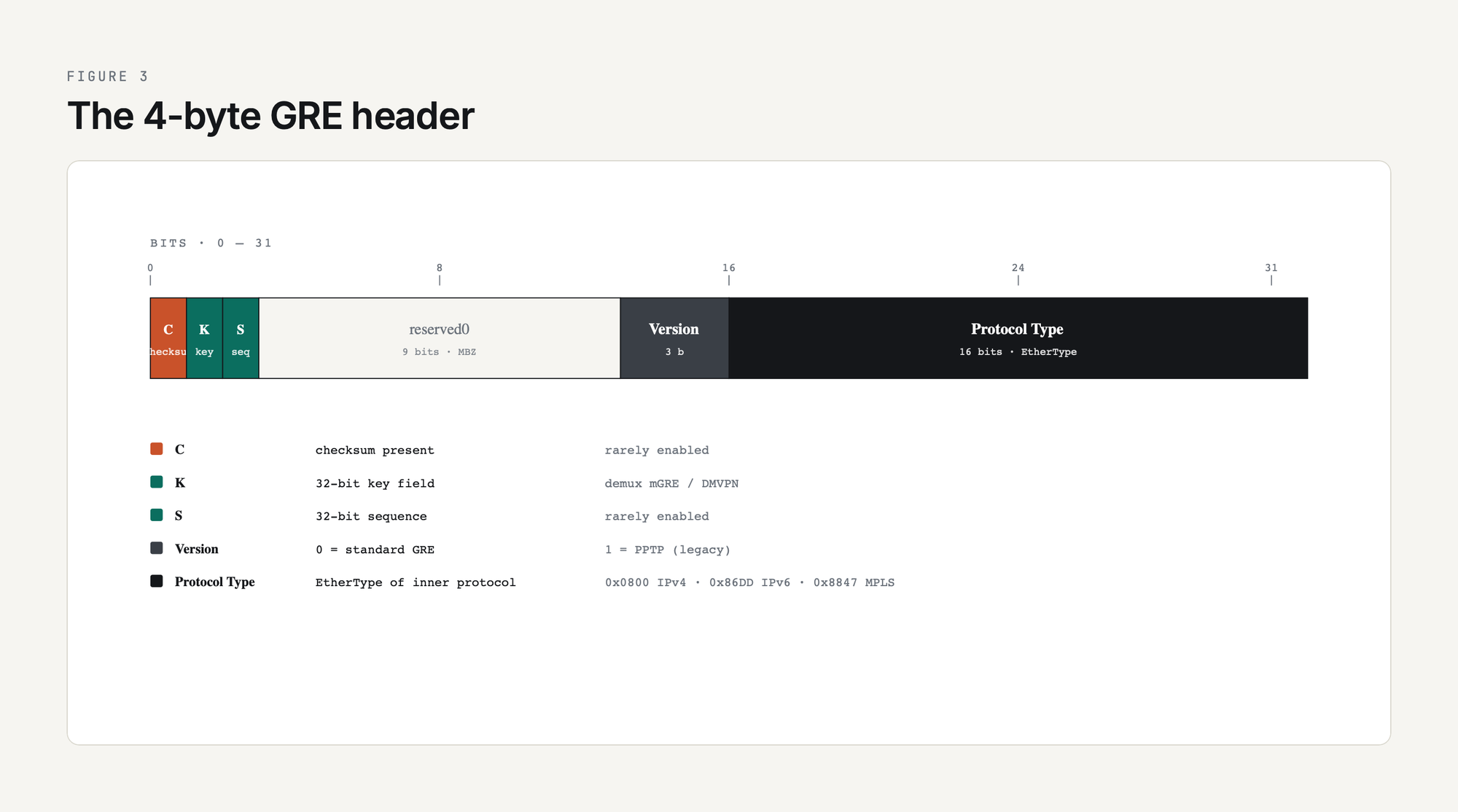
GRE Header Fields
The 4-byte mandatory GRE header has five flag bits and a Protocol Type field. The flags decide whether optional fields follow:
The Protocol Type field is what makes GRE generic. By advertising the EtherType of the inner protocol, GRE can carry anything the receiver knows how to decode. Most of the time you are looking at 0x0800 (IPv4) or 0x86DD (IPv6) and the rest of the flags are zero. The Key field becomes important when you build multipoint GRE for DMVPN; see mGRE and DMVPN Introduction for how the same tunnel source can serve many destinations.
Configuration on Cisco IOS XE: Minimum Viable GRE
The smallest working GRE tunnel between two Cisco routers:
! ---- R1 ----
interface Tunnel0
 ip address 10.0.0.1 255.255.255.252
 tunnel source 198.51.100.1
 tunnel destination 203.0.113.1
 tunnel mode gre ip
!
! ---- R2 ----
interface Tunnel0
 ip address 10.0.0.2 255.255.255.252
 tunnel source 203.0.113.1
 tunnel destination 198.51.100.1
 tunnel mode gre ip
Two interface stanzas, four lines of relevant config each. The tunnel source and destination must be IPs that the underlay routing table can reach (typically internet-routable addresses on each end, or any reachable IP if the tunnel rides over a private WAN). The 10.0.0.0/30 inside the tunnel is the overlay; pick anything you like as long as both ends agree.
Verification on R1:
R1#show interface Tunnel0
Tunnel0 is up, line protocol is up
  Hardware is Tunnel
  Description: GRE tunnel to R3 (source Lo0, dest 10.255.0.3)
  Internet address is 10.30.30.1/30
  MTU 17916 bytes, BW 100 Kbit/sec, DLY 50000 usec,
     reliability 255/255, txload 1/255, rxload 1/255
  Encapsulation TUNNEL, loopback not set
  Keepalive set (5 sec), retries 3
  Tunnel linestate evaluation up
  Tunnel source 10.255.0.1 (Loopback0), destination 10.255.0.3
   Tunnel Subblocks:
      src-track:
         Tunnel0 source tracking subblock associated with Loopback0
          Set of tunnels with source Loopback0, 1 member, on interface <OK>
  Tunnel protocol/transport GRE/IP
    Key disabled, sequencing disabled
    Checksumming of packets disabled
  Tunnel TTL 255, Fast tunneling enabled
  Tunnel transport MTU 1476 bytes
  Tunnel state info:
    State change to up   : May 11 2026 06:32:49
The output is from the PingLabz GRE Reference Lab where R1's Tunnel0 is sourced from Loopback0 (10.255.0.1) and destined for R3's Loopback0 (10.255.0.3). The Tunnel source 10.255.0.1 (Loopback0) line is the production-style flavour - sourcing from a loopback rather than a physical interface means the tunnel survives any single underlay interface failure as long as the underlay routes to that loopback. Tunnel transport MTU 1476 is Cisco doing the math: 1500 underlay minus 24 GRE+IP overhead. Tunnel linestate evaluation up is the modern IOS XE per-tunnel state tracker confirming the destination is reachable and the tunnel is forwarding. Note that line-protocol-up does not actually mean the remote end is processing traffic - a GRE tunnel will show up / up as long as the underlay route to the destination is reachable, even if the remote router is offline. That is exactly the problem keepalives were invented to solve. Full lab walkthrough at GRE Tunnel Configuration: Step-by-Step Cisco IOS-XE Lab.
Sourcing Tunnel0 from a loopback (as the lab does) means the underlay needs a route to that loopback. In the lab R1 has a static route to R3's loopback via the transit router; in production this is normally the IGP's job. The IP routing table on R1 makes the resolution chain explicit:
R1#show ip route
      10.0.0.0/8 is variably subnetted, 4 subnets, 2 masks
C        10.30.30.0/30 is directly connected, Tunnel0
L        10.30.30.1/32 is directly connected, Tunnel0
C        10.255.0.1/32 is directly connected, Loopback0
S        10.255.0.3/32 [1/0] via 192.0.2.2
      192.0.2.0/24 is variably subnetted, 2 subnets, 2 masks
C        192.0.2.0/30 is directly connected, Ethernet0/0
L        192.0.2.1/32 is directly connected, Ethernet0/0
The S 10.255.0.3/32 [1/0] via 192.0.2.2 line is the underlay path that resolves the tunnel destination. Take it away or let the inside-the-tunnel routing protocol be the only source of that route, and you create the recursive-routing scenario covered at the end of this guide.
Routing Over GRE
The reason most GRE tunnels exist is to carry a routing protocol. Plain static routes do not need GRE; if you have a static route to the remote network via the underlay, you do not need a tunnel. GRE earns its keep when you want OSPF, EIGRP, or BGP to form a neighbor relationship across an underlay that does not natively support it.
The pattern is the same regardless of routing protocol:
- Bring up the GRE tunnel.
- Put the tunnel interface in the routing protocol's interface set (
networkstatement,ip ospfcommand, EIGRPnetworkcommand, or BGPneighborusing the tunnel-overlay IP). - Watch the neighbor come up. From the routing protocol's perspective the tunnel looks like any other point-to-point link.
OSPF over GRE is the most common case because OSPF needs multicast (224.0.0.5 / 224.0.0.6) for hellos and DR election. The internet does not forward multicast; GRE wraps the multicast in unicast and the problem disappears. EIGRP behaves the same way. iBGP over GRE is common in hub-and-spoke designs where the overlay carries the iBGP mesh. Worked configs and gotchas (recursive routing, OSPF network types, EIGRP delay tweaking) are at Routing Protocols Over GRE: OSPF, EIGRP, BGP.
OSPF over the lab's tunnel comes up FULL with R3 (the only neighbor on the tunnel), and the neighbor address is R3's Tunnel0 IP (10.30.30.2), not its loopback - because OSPF talks to the IP on the interface it's running on:
R1#show ip ospf neighbor

Neighbor ID     Pri   State           Dead Time   Address         Interface
10.255.0.3        0   FULL/  -        00:00:36    10.30.30.2      Tunnel0
Priority 0 and state suffix - are the OSPF point-to-point network-type defaults; there is no DR election on a Tunnel0 P2P link. A ping across the overlay sourced from R1's loopback confirms end-to-end reachability over GRE:
R1#ping 10.255.0.3 source 10.255.0.1
Type escape sequence to abort.
Sending 5, 100-byte ICMP Echos to 10.255.0.3, timeout is 2 seconds:
Packet sent with a source address of 10.255.0.1
!!!!!
Success rate is 100 percent (5/5), round-trip min/avg/max = 2/2/3 ms
One thing to plan for: any routing protocol you run inside the tunnel must not use the tunnel to learn the route to the tunnel destination itself. That is recursive routing, the tunnel will flap, and the symptom is "GRE tunnel keeps going up and down every few minutes." Use a static route to the tunnel destination via the underlay, or filter the underlay's IP out of the inside-the-tunnel routing protocol. The lab below shows what happens when you forget.
GRE Keepalives
Vanilla GRE has no liveness check. The tunnel interface stays up / up as long as the local router can route to the configured tunnel destination. If the remote router crashes, is rebooted, or has a software fault that stops it processing GRE, the local end has no way to know and traffic black-holes.
Cisco's GRE keepalives (a Cisco extension, not in the original RFC 2784 but widely adopted by other vendors) fix this by periodically sending a small GRE-encapsulated packet whose inner IP is addressed back to the sender. The remote router does not have to do anything special; it just routes the inner packet according to its routing table, which sends it back through the tunnel to the sender. If keepalives stop returning, the local end declares the tunnel down.
interface Tunnel0
 keepalive 10 3
That tells the router: send a keepalive every 10 seconds, and declare the tunnel down after 3 missed responses (so 30 seconds of no response). Defaults are 10 seconds and 3 retries. Keepalives are unidirectional - each end runs them independently - and they have a subtle interaction with IPsec that catches engineers out, which is the subject of the dedicated GRE Tunnel Keepalives Explained article.
A few seconds of debug tunnel keepalive on R1 shows exactly what travels each way. Note the trick: R1 builds the keepalive with INNER source 10.255.0.3 (the remote loopback) and INNER dest 10.255.0.1 (its own loopback), so when R3 receives and decapsulates, it sees an ordinary IP packet from 10.255.0.3 to 10.255.0.1 and forwards it back through the tunnel:
R1#debug tunnel keepalive
Tunnel keepalive debugging is on

*May 11 06:35:34.539: Tunnel0: sending keepalive, 10.255.0.3->10.255.0.1 (len=24 ttl=255), counter=1
*May 11 06:35:34.542: Tunnel0: keepalive received, 10.255.0.3->10.255.0.1 (len=24 ttl=252), resetting counter
*May 11 06:35:39.540: Tunnel0: sending keepalive, 10.255.0.3->10.255.0.1 (len=24 ttl=255), counter=1
*May 11 06:35:39.543: Tunnel0: keepalive received, 10.255.0.3->10.255.0.1 (len=24 ttl=252), resetting counter
*May 11 06:35:44.540: Tunnel0: sending keepalive, 10.255.0.3->10.255.0.1 (len=24 ttl=255), counter=1
*May 11 06:35:44.544: Tunnel0: keepalive received, 10.255.0.3->10.255.0.1 (len=24 ttl=252), resetting counter

R1#undebug all
The TTL falls from 255 (R1 originates) to 252 (R1 receives back). That is exactly the 3-hop round-trip across the underlay (R1 -> R2 -> R3, decap, forward back across the same path). The counter resets to zero on every successful return - if three consecutive sends miss their return, the tunnel goes down with a "tunnel keepalive failed" log.
MTU, Fragmentation, and MSS Clamping
The single most common operational problem with GRE tunnels is MTU. Every encapsulation adds bytes, and when the resulting packet is too big to fit in the underlay path MTU, something must give: either the packet is fragmented, or it is dropped with an ICMP "fragmentation needed" message, or, in the most painful case, it is silently dropped by an underlay device that filters ICMP.
The math for plain GRE over IPv4 with a 1500-byte underlay:
Add IPsec on top in tunnel mode and you lose another 50-60 bytes. The two-line fix that prevents 90 percent of GRE MTU pain on Cisco:
interface Tunnel0
 ip mtu 1400
 ip tcp adjust-mss 1360
ip mtu 1400 tells the tunnel interface to fragment IP packets larger than 1400 bytes before encapsulation, leaving headroom for IPsec overhead. ip tcp adjust-mss 1360 rewrites the MSS value in TCP SYN packets so endpoints negotiate a segment size that fits inside the tunnel without requiring fragmentation in the first place. Full breakdown of the math, when to set what value, and how to debug the symptoms (large pings fail, small ones succeed; HTTPS works for some sites but not others) is at GRE MTU and Fragmentation.
Security: GRE Has None - Use IPsec
GRE was designed for trusted networks. The header has no authentication, no integrity check (the optional checksum is integrity in the weakest sense), and no encryption. Anyone with packet-capture access on the underlay path can read every byte of every inner packet.
For lab and private-WAN use that is fine. For anything traversing the public internet it is not. The standard pattern is GRE inside IPsec: GRE provides the encapsulation and routing-protocol multicast support, IPsec provides confidentiality, integrity, and authentication. Modern IOS XE deployments use IPsec profiles attached to the tunnel interface (the tunnel protection ipsec profile command), which is cleaner than the older crypto map approach. The full configuration walkthrough is at GRE over IPsec: When and How to Combine Them.
For the framework on when to use plain GRE, GRE-over-IPsec, IPsec alone, or something else (VXLAN, WireGuard, SD-WAN overlays), see GRE vs IPsec vs GRE-over-IPsec: Which Tunnel Type?.
Multipoint GRE and DMVPN
Standard GRE is point-to-point: one tunnel source, one tunnel destination, one neighbor. That works for two sites. For 50 branches connecting to two hubs, you do not want 100 manually configured GRE tunnels.
Multipoint GRE (mGRE, tunnel mode gre multipoint) lets a single tunnel interface have many remote destinations. Combined with NHRP (Next Hop Resolution Protocol) for dynamic mapping and IPsec for encryption, mGRE becomes DMVPN (Dynamic Multipoint VPN), the Cisco standard for hub-and-spoke and spoke-to-spoke overlays. DMVPN Phase 1 is hub-and-spoke only (spoke-to-spoke goes through the hub). Phase 2 enables direct spoke-to-spoke after a hub-mediated NHRP resolution. Phase 3 (the modern default) uses NHRP shortcut switching for efficient direct paths.
DMVPN deserves its own cluster, but the GRE-side foundation is just a multipoint tunnel interface and an NHRP map command. The introduction lives at mGRE and DMVPN Introduction.
GRE Across Vendors
GRE is a standard and every major vendor implements it. Cisco gets the most coverage in this guide because of its CLI ubiquity, but the wire format is the same everywhere. Quick orientation:
Configuration syntax differs, behavior of optional fields (Key, Sequence) differs, and keepalive interop between Cisco and non-Cisco kit can be flaky because keepalives are a Cisco extension. The Linux deep dive is at GRE on Linux: ip tunnel add Commands.
Troubleshooting: The Common Failures
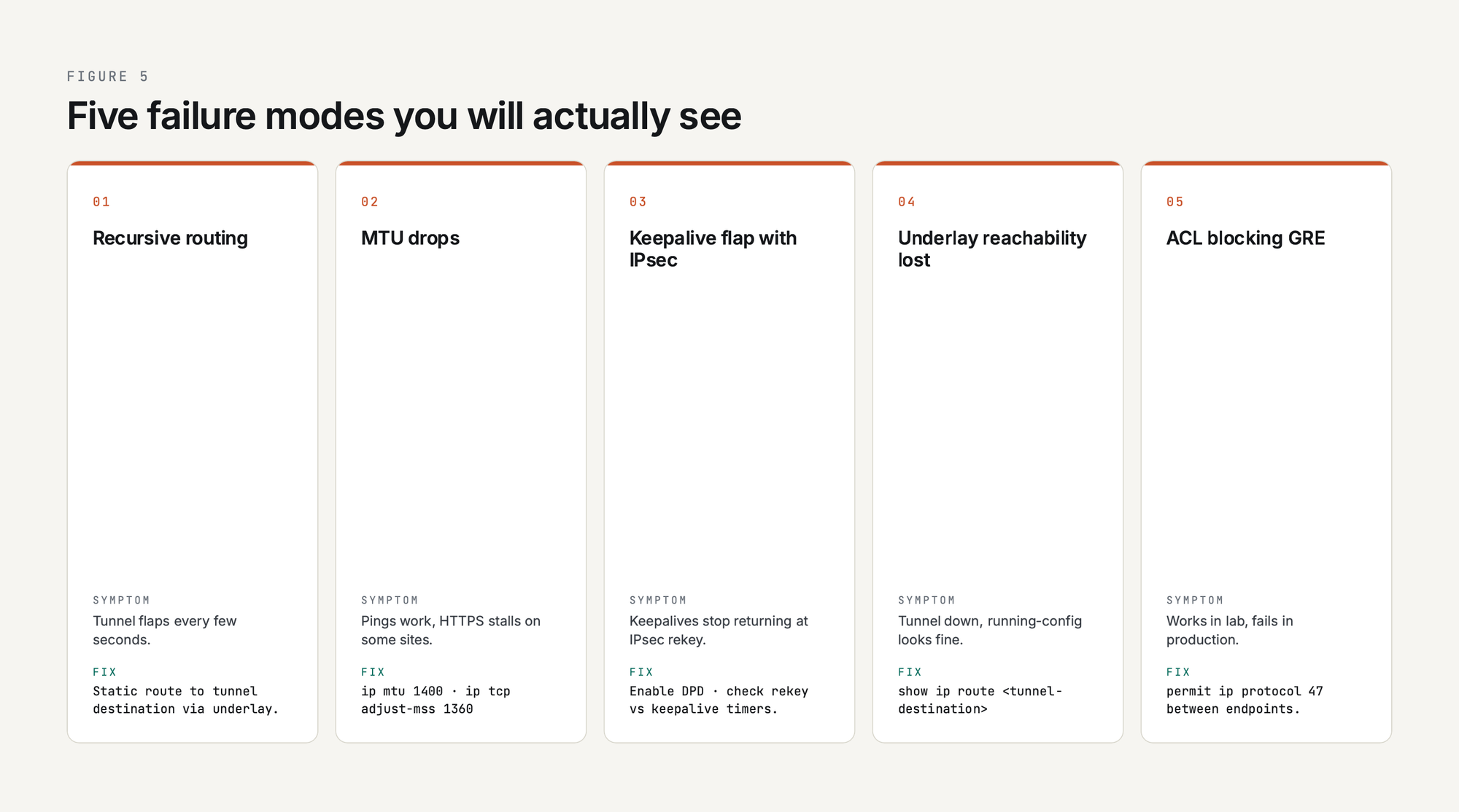
The five GRE failure modes you will actually see in production:
- Recursive routing. The route to the tunnel destination is learned through the tunnel itself. The tunnel comes up, the routing protocol learns a better path to the underlay through the tunnel, the tunnel goes down, the routing protocol forgets, and the cycle repeats. Symptom: tunnel flaps every few seconds. Fix: static route to the tunnel destination via the underlay, or distribute-list the underlay IP out of the tunnel-side routing protocol.
- MTU drops. Small packets work, large packets do not. Pings work, HTTPS to certain sites stalls. Fix:
ip mtu 1400andip tcp adjust-mss 1360on the tunnel interface. - Keepalive flap with IPsec. GRE keepalives stop returning when the IPsec tunnel rekeys, or when one direction's IPsec SA dies. Fix: enable IPsec DPD (Dead Peer Detection) and check keepalive intervals against rekey timers.
- Underlay reachability lost. The local end can no longer route to the tunnel destination IP. Tunnel interface goes down even though "show running-config" looks correct. Fix: check the underlay routing table with
show ip route <tunnel-destination>. - ACL blocking GRE. A stateful firewall in the path drops protocol 47 because it does not match TCP, UDP, or ICMP. Fix: add an explicit permit for IP protocol 47 between tunnel endpoints. This catches a lot of greenfield deployments where the underlay firewall was provisioned without knowledge of the GRE plan.
Recursive routing is the failure mode every GRE engineer remembers, and the lab can reproduce it on cue. Starting from the working topology - tunnel up, OSPF FULL across it, an underlay static route to the tunnel destination - simply remove the underlay static. R1's only remaining path to 10.255.0.3 is the OSPF route learned over Tunnel0 itself, and IOS detects the loop within a few seconds:
R1(config)#no ip route 10.255.0.3 255.255.255.255 192.0.2.2

! ~30 seconds later, syslog reports:
*May 11 06:36:16.894: %ADJ-5-PARENT: Midchain parent maintenance for IP
                        midchain out of Tunnel0 - looped chain attempting to stack
*May 11 06:36:19.540: %TUN-5-RECURDOWN: Tunnel0 temporarily disabled
                        due to recursive routing
*May 11 06:36:19.540: %LINEPROTO-5-UPDOWN: Line protocol on Interface
                        Tunnel0, changed state to down
*May 11 06:36:19.542: %OSPF-5-ADJCHG: Process 1, Nbr 10.255.0.3 on Tunnel0
                        from FULL to DOWN, Neighbor Down: Interface down or detached

R1#show interface Tunnel0 | include line protocol|linestate|destination
Tunnel0 is up, line protocol is down
  Tunnel linestate evaluation down - no output interface
  Tunnel source 10.255.0.1 (Loopback0), destination 10.255.0.3
The %TUN-5-RECURDOWN: Tunnel0 temporarily disabled due to recursive routing line is the canonical "GRE blew up" log every engineer recognises. The supporting %ADJ-5-PARENT ... looped chain attempting to stack message is the CEF adjacency subsystem detecting the recursion at the forwarding-plane level - it spotted that resolving the tunnel's next-hop would require traversing the tunnel itself. Restoring the underlay static reverses the failure within seconds: the chain unwinds, the tunnel comes back up, and OSPF re-converges.
The full debug walkthrough with debug tunnel, debug ip packet detail, and packet captures of the problem cases is at GRE Tunnel Troubleshooting Guide.
The Full GRE Cluster, in Reading Order
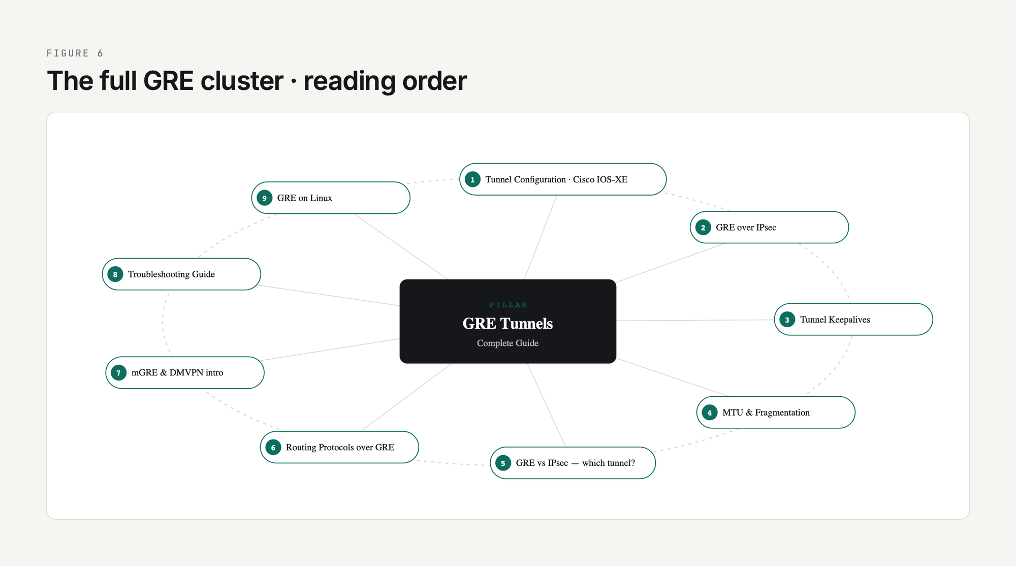
The articles in this cluster, in the order they make sense to read:
- GRE Tunnel Configuration: Step-by-Step Cisco IOS-XE Lab
- GRE over IPsec: When and How to Combine Them
- GRE Tunnel Keepalives Explained
- GRE MTU and Fragmentation: Fixing Tunnel Packet Loss
- GRE vs IPsec vs GRE-over-IPsec: Which Tunnel Type?
- Routing Protocols Over GRE: OSPF, EIGRP, BGP
- mGRE and DMVPN Introduction
- GRE Tunnel Troubleshooting Guide
- GRE on Linux: ip tunnel add Commands
This list grows as the cluster expands. Bookmark this page; the cluster is the canonical PingLabz reference for GRE.
Hands-on GRE - build a real tunnel
Configure a GRE Tunnel0 between two Cisco routers sourced from loopbacks, with R2 as a transparent transit. Capture the single-hop traceroute that defines an overlay. Part of the 12-lab CCNA Network Fundamentals cluster. Open the PingLabz CCNA Labs library.
Frequently Asked Questions
What is the GRE protocol number?
GRE is IP protocol 47, assigned by IANA. That is the value in the Protocol field of the outer IP header. GRE is not a TCP or UDP protocol, so it has no port number. If a firewall in the path filters by TCP/UDP port and does not have an explicit allow for IP protocol 47, GRE packets get dropped at that hop. This is the single most common reason a GRE tunnel works in lab and fails in production.
Is a GRE tunnel secure?
No. GRE has no encryption, no authentication, and no integrity protection. Anyone who can capture packets on the underlay path can read every byte of the inner traffic. That is why production deployments wrap GRE inside IPsec (or run an alternative like WireGuard or an SD-WAN overlay). GRE alone is appropriate for trusted networks (private MPLS, internal data center) but not for the public internet.
Is GRE a VPN?
GRE is a tunnel, which is one of the components a VPN is built from, but GRE alone is not a VPN in the security sense. A VPN, as the term is normally used, implies confidentiality (encryption) and authentication. GRE provides neither. GRE-over-IPsec is a VPN. Plain GRE is a tunnel that happens to look topologically like a VPN.
GRE vs IPsec - which one should I use?
If you need encryption and only need to carry unicast IP, use IPsec alone (in tunnel mode). If you need to carry multicast (so OSPF / EIGRP can form neighbors over the tunnel) or you need to carry non-IP protocols, use GRE. If you need encryption and multicast support, use GRE over IPsec. The decision tree is at GRE vs IPsec vs GRE-over-IPsec: Which Tunnel Type?.
Is GRE a Cisco proprietary protocol?
No. Cisco invented GRE and was the first vendor to ship it, but the protocol was standardized as RFC 1701 in 1994 and updated as RFC 2784 in 2000. RFC 2890 added optional Key and Sequence Number extensions. Every major networking vendor (Juniper, Arista, Linux, FortiGate, MikroTik, Palo Alto) implements GRE as an interoperable standard. Some specific extensions, like Cisco GRE keepalives, are vendor-specific and may not interoperate cleanly across vendors.
How much overhead does GRE add to each packet?
Plain GRE over IPv4 adds 24 bytes per packet: 20 bytes of outer IPv4 header plus 4 bytes of GRE header. Enabling Key, Sequence, or Checksum adds 4 bytes per field. GRE over IPv6 has 40 bytes of outer IPv6 header plus 4 bytes of GRE for 44 bytes total. Add IPsec in tunnel mode and you lose another 50-60 bytes depending on the cipher. That is why ip mtu 1400 on the tunnel interface is the safe default - it leaves headroom for any encryption you add later.
Key Takeaways
GRE is the simplest possible tunnel: an outer IP header, a 4-byte GRE header, and your original packet. It carries multicast over unicast underlays, runs routing protocols across paths that would otherwise not support them, and gives you a clean Layer 3 next-hop between two endpoints regardless of how complicated the underlay is. It has been a network-engineer staple for three decades because it does one thing well, almost never breaks, and works the same way on every vendor.
If you take one thing away from this guide, take this: GRE without IPsec is a private-network tool, GRE with IPsec is the production tunnel of choice, and the operational pain of GRE always reduces to either MTU or recursive routing. Set ip mtu 1400, run keepalive 10 3, route the tunnel destination statically through the underlay, and you have eliminated 80 percent of the failure modes before you have a single user complaint. Bookmark this page, work through the cluster articles in order, and lab every design decision before you ship it. GRE is simple. Production GRE done well is the result of caring about the parts that look simple.