This is the step-by-step Cisco IOS XE lab walkthrough for building a GRE tunnel between two routers. We will go from a blank config to a verified, traffic-passing tunnel, then add the production knobs (MTU clamping, keepalives, OSPF over the tunnel) one at a time. Every command is shown with the show output you should see if it worked. If a step does not match what you see, you have a clear place to start debugging.
The lab is part of the PingLabz GRE Tunnels: The Complete Guide cluster. If you want the protocol theory before the config, start there. Otherwise, paste the configs into IOS XE and follow along.
Lab Topology
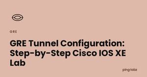
Two Cisco IOS XE routers (CSR1000v, Catalyst 8000v, ISR4000, or any IOS XE platform with IP Base/Advanced IP Services). The routers are connected through an underlay network that simulates the public internet, with no end-to-end private IP routing.
Goal: get a host on R1's LAN (192.168.1.0/24) to reach a host on R2's LAN (192.168.2.0/24) through the GRE tunnel, with no underlay route to the private LAN networks.
Step 1: Verify Underlay Reachability
Before building the tunnel, confirm the two routers can reach each other on their underlay IPs. If the underlay is broken, no GRE config in the world will help.
R1# ping 203.0.113.1 source 198.51.100.1
Type escape sequence to abort.
Sending 5, 100-byte ICMP Echos to 203.0.113.1, timeout is 2 seconds:
Packet sent with a source address of 198.51.100.1
!!!!!
Success rate is 100 percent (5/5), round-trip min/avg/max = 4/5/9 ms
If this ping fails, fix the underlay first. Check show ip route 203.0.113.1 to confirm the routing table has a path. If the underlay traverses a firewall, confirm ICMP is permitted between the two underlay IPs.
Step 2: Configure the Tunnel Interfaces
Both ends need a Tunnel interface with matching tunnel source / destination, an IP address on the overlay, and tunnel mode set to GRE over IP.
! ---- R1 ----
R1(config)# interface Tunnel0
R1(config-if)# ip address 10.0.0.1 255.255.255.252
R1(config-if)# tunnel source 198.51.100.1
R1(config-if)# tunnel destination 203.0.113.1
R1(config-if)# tunnel mode gre ip
R1(config-if)# no shutdown

! ---- R2 ----
R2(config)# interface Tunnel0
R2(config-if)# ip address 10.0.0.2 255.255.255.252
R2(config-if)# tunnel source 203.0.113.1
R2(config-if)# tunnel destination 198.51.100.1
R2(config-if)# tunnel mode gre ip
R2(config-if)# no shutdown
Two notes on the source. First, you can use an interface name (tunnel source GigabitEthernet1) instead of an IP. The router takes the primary IP of that interface as the source. Using the interface name is more resilient to IP renumbering. Second, in production deployments where the underlay IP changes (DHCP from the ISP, for example), use a Loopback interface as the tunnel source and run a static route or routing protocol on the underlay so the loopback is reachable from the far end. That gives you a stable tunnel source IP regardless of underlay churn.
tunnel mode gre ip is actually the IOS XE default - if you create a Tunnel interface and do not specify a mode, you get GRE over IPv4. Setting it explicitly is good hygiene because it documents intent and protects you when the default changes (it has, between IOS versions).
Step 3: Verify the Tunnel Comes Up
R1# show interface Tunnel0
Tunnel0 is up, line protocol is up
Hardware is Tunnel
Internet address is 10.0.0.1/30
MTU 17916 bytes, BW 100 Kbit/sec, DLY 50000 usec,
reliability 255/255, txload 1/255, rxload 1/255
Encapsulation TUNNEL, loopback not set
Keepalive not set
Tunnel linestate evaluation up
Tunnel source 198.51.100.1, destination 203.0.113.1
Tunnel protocol/transport GRE/IP
Key disabled, sequencing disabled
Checksumming of packets disabled
Tunnel TTL 255, Fast tunneling enabled
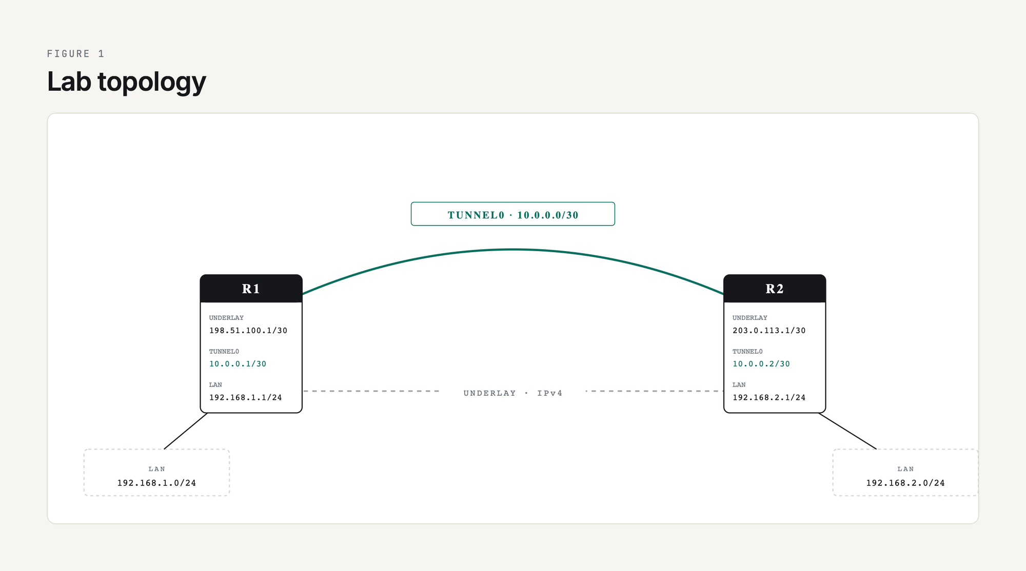
Tunnel transport MTU 1476 bytes
Tunnel transmit bandwidth 8000 (kbps)
Tunnel receive bandwidth 8000 (kbps)Three things to look for in this output. Tunnel0 is up, line protocol is up means the configured tunnel source IP exists locally and the underlay route to the destination is in the routing table. Tunnel transport MTU 1476 bytes is IOS XE doing the math: 1500 - 24 = 1476. Keepalive not set tells you the tunnel will stay up even if the remote end becomes unreachable; we will fix that in step 6.
If line protocol is down, run show ip route <tunnel-destination> to confirm there is a route to the far end's underlay IP. If there is no route, the tunnel will not come up.
Step 4: Ping Across the Overlay
R1# ping 10.0.0.2
Type escape sequence to abort.
Sending 5, 100-byte ICMP Echos to 10.0.0.2, timeout is 2 seconds:
!!!!!
Success rate is 100 percent (5/5), round-trip min/avg/max = 4/5/8 ms
If this fails but the underlay ping in Step 1 worked, the most common cause is a stateful firewall in the underlay path that does not have an explicit allow rule for IP protocol 47 (GRE). The firewall sees a packet that is neither TCP, UDP, nor ICMP and drops it by default. Add an explicit permit, retest, and the tunnel ping will work.
The other common cause is a typo in tunnel destination on either end, especially when copying configs. Double-check the IPs match what you expect with show interface tunnel0 | include source|destination.
Step 5: Make the LAN Networks Reachable Through the Tunnel
The tunnel works overlay-to-overlay (10.0.0.1 to 10.0.0.2), but neither router knows how to reach the other's LAN (192.168.x.0/24). Two options: static routes, or a routing protocol over the tunnel. For a two-site lab, static routes are simplest.
R1(config)# ip route 192.168.2.0 255.255.255.0 10.0.0.2

R2(config)# ip route 192.168.1.0 255.255.255.0 10.0.0.1
Verify with a sourced ping that simulates LAN traffic:
R1# ping 192.168.2.1 source 192.168.1.1
Type escape sequence to abort.
Sending 5, 100-byte ICMP Echos to 192.168.2.1, timeout is 2 seconds:
Packet sent with a source address of 192.168.1.1
!!!!!
Success rate is 100 percent (5/5), round-trip min/avg/max = 4/5/8 ms
The packet traverses R1's LAN interface, gets routed into Tunnel0 by the static route, picks up the GRE+outer-IP encapsulation, traverses the underlay as a unicast IP packet, arrives at R2, gets decapsulated, and is routed out R2's LAN interface to its destination. That whole pipeline runs with no per-packet state on either router beyond the routing table.
Step 6: Add Keepalives
Without keepalives, the tunnel interface stays up as long as the underlay route to the tunnel destination exists. If R2 crashes, the local end has no idea and traffic black-holes for as long as it takes the underlay routing protocol to converge (which may be never if the route is static).
R1(config)# interface Tunnel0
R1(config-if)# keepalive 10 3

R2(config)# interface Tunnel0
R2(config-if)# keepalive 10 3
keepalive 10 3 means send a keepalive every 10 seconds and declare the tunnel down after 3 missed responses. Verify:
R1# show interface Tunnel0 | include Keepalive
  Keepalive set (10 sec), retries 3
Keepalives are a Cisco extension to GRE that work by sending a small GRE-encapsulated ICMP-like packet whose inner header tells the remote router to send it back. If you are tunneling between Cisco and a non-Cisco device, do not assume keepalives interoperate; test before trusting them. The full mechanism is at GRE Tunnel Keepalives Explained.
Step 7: Tune MTU for Production Traffic
The default IP MTU on a Tunnel interface is the underlay MTU minus the GRE+IP overhead (1476 for a 1500-byte underlay). That works for plain GRE but does not leave room if you later add IPsec encryption, and it does not solve the universal problem of TCP endpoints negotiating a segment size that is too large.
The two-line fix:
R1(config)# interface Tunnel0
R1(config-if)# ip mtu 1400
R1(config-if)# ip tcp adjust-mss 1360

R2(config)# interface Tunnel0
R2(config-if)# ip mtu 1400
R2(config-if)# ip tcp adjust-mss 1360
ip mtu 1400 tells the router to fragment IP packets larger than 1400 bytes before they hit the tunnel encapsulation, which leaves 100 bytes of headroom for IPsec or any other future overhead. ip tcp adjust-mss 1360 rewrites the MSS value in TCP SYN packets passing through the tunnel so endpoints negotiate a segment size that already fits, eliminating fragmentation rather than just handling it. The math, the symptoms of MTU misconfiguration, and the deeper debugging tools are at GRE MTU and Fragmentation: Fixing Tunnel Packet Loss.
Step 8: Run OSPF Over the Tunnel
Static routes work for two sites. For three or more, swap to a routing protocol so new networks are learned dynamically. OSPF is the most common choice over GRE because it needs multicast, which GRE happily carries.
R1(config)# router ospf 1
R1(config-router)# network 10.0.0.0 0.0.0.3 area 0
R1(config-router)# network 192.168.1.0 0.0.0.255 area 0
R1(config-router)# passive-interface GigabitEthernet2

R2(config)# router ospf 1
R2(config-router)# network 10.0.0.0 0.0.0.3 area 0
R2(config-router)# network 192.168.2.0 0.0.0.255 area 0
R2(config-router)# passive-interface GigabitEthernet2
Verify the neighbor:
R1# show ip ospf neighbor

Neighbor ID     Pri   State           Dead Time   Address         Interface
10.0.0.2          1   FULL/DROTHER    00:00:39    10.0.0.2        Tunnel0
Once the neighbor is FULL, R1 has learned 192.168.2.0/24 dynamically through OSPF and you can remove the static routes from Step 5. Multiple sites can now be added by configuring more tunnels to a hub and putting them all in OSPF area 0.
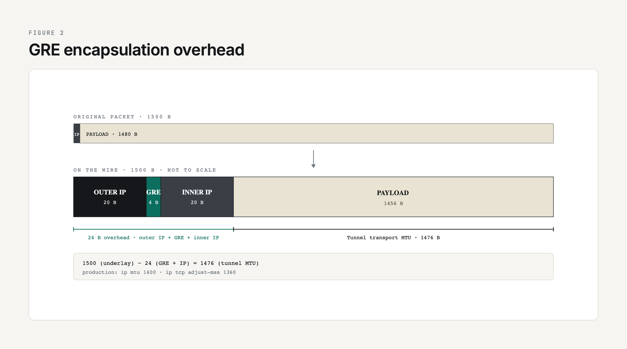
One thing to watch: do not let OSPF (or any routing protocol you run inside the tunnel) advertise a route to the tunnel destination IP. If R1 learns the route to 203.0.113.1 through Tunnel0 itself, the tunnel goes recursive and flaps. Use a static underlay route to the tunnel destination, or filter the underlay IP out of the tunnel-side routing protocol with a distribute-list. The full coverage of OSPF, EIGRP, and BGP over GRE (including the recursive routing fix) is at Routing Protocols Over GRE: OSPF, EIGRP, BGP.
Final Production-Style Config
Putting it all together, the production-style R1 config (with keepalives, MTU clamping, and OSPF):
interface Tunnel0
 ip address 10.0.0.1 255.255.255.252
 ip mtu 1400
 ip tcp adjust-mss 1360
 tunnel source 198.51.100.1
 tunnel destination 203.0.113.1
 tunnel mode gre ip
 keepalive 10 3
!
router ospf 1
 network 10.0.0.0 0.0.0.3 area 0
 network 192.168.1.0 0.0.0.255 area 0
 passive-interface GigabitEthernet2
!
ip route 203.0.113.1 255.255.255.255 198.51.100.2
That last static route is the recursive-routing safety net: it tells R1 to reach R2's tunnel destination IP via the underlay next-hop, never via the tunnel itself.
If the Tunnel Does Not Come Up
The five most common failure modes and how to spot them:
show ip route <tun-dest>show ip route <tun-dest> shows Tunnel0 as the next-hopping 192.168.2.1 size 1400 df-bit; lower MTU until it succeedsdebug ip ospf hello on both endsFor a deeper dive into each of these failure modes with packet captures and debug command output, see GRE Tunnel Troubleshooting Guide.
Summary
A working GRE tunnel on Cisco IOS XE is eight lines of config: a Tunnel interface with an IP, a source, a destination, a mode, and a keepalive, plus MTU clamping and either static routes or a routing protocol on top. Every step in this lab maps to a piece of that config and a verification command that proves it worked. The trick is not in the syntax; the trick is in remembering which knobs to set in production (keepalives, MTU, recursive-route protection) and what each one prevents.
If you are now ready to add encryption, see GRE over IPsec. If you want to scale this from two sites to many, see mGRE and DMVPN Introduction. Either way, you have the plumbing: the rest is policy.