This is Part 1 of the PingLabz 9800 Wireless Labs series. Over the next several posts (and matching YouTube videos), we build a complete Catalyst 9800-CL wireless environment from scratch in Cisco Modeling Labs - starting with an empty canvas and ending with wireless clients passing traffic through a WLC we configured line by line. If you are studying for CCNP ENCOR/ENWLSI or just want hands-on 9800 experience without buying hardware, this series is for you. For the broader wireless fundamentals behind everything we do here, see the complete wireless guide.
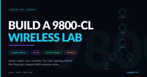
In this first part we build the lab topology itself: the 9800-CL controller, a small wired campus underneath it, a bridge to a physical access point sitting on your desk, and CML's simulated wireless AP and client nodes. No device configs yet - that starts in Part 2.
Video coming soon - the YouTube embed will land here when Part 1 is live.
What You Need
Everything in this lab runs on Cisco Modeling Labs (CML 2.9 or later) using reference platform images. The node mix was chosen deliberately: the 9800-CL is the one heavy VM in the lab, so everything around it uses the lightweight IOL XE images (Docker-based, boot in seconds, tiny RAM footprint) instead of full VMs like the Catalyst 9000v or Catalyst 8000v.
WLC1 (cat9800) - Catalyst 9800-CL on IOS XE 17.18, the wireless LAN controller
EDGE-RTR1 (iol-xe) - IOL XE router, WAN edge and simulated internet
CORE-SW1 (ioll2-xe) - IOL XE L2 switch, the L3 core: SVIs and future DHCP
ACCESS-SW1 (ioll2-xe) - IOL XE L2 switch, access layer for the APs
EXT-BRIDGE (external_connector) - bridge mode, connects a physical AP into the lab
SIM-AP1 (wireless-ap) - Ubuntu + hostapd, simulated Wi-Fi access point
WCLIENT1 (wireless-client) - Ubuntu + wpa_supplicant, simulated Wi-Fi client
The whole topology, including the 9800-CL, fits comfortably in a CML instance with 16 GB of free RAM. If you ran the same design with Catalyst 9000v switches you would need roughly 18 GB per switch, which is why we don't.
The Topology
            EDGE-RTR1 (IOL-XE)
                | e0/0 - e0/0
            CORE-SW1 (IOL-L2)----- e0/2 - Gi1 ----- WLC1 (9800-CL)
                | e0/1 - e0/0
            ACCESS-SW1 (IOL-L2)
            /        \
   e0/1 (VLAN 30)   e0/2 (VLAN 20)
        |                 |
   EXT-BRIDGE         SIM-AP1 (hostapd)
   (physical AP)          | ens3 - ens2
                      WCLIENT1
A deliberately small campus: one router, one core, one access switch. It is enough to demonstrate every core 9800 concept (trunking the WLC, separating management from client traffic, AP joins across an L2/L3 boundary) without burying the wireless content under a big wired build.
Link Map
EDGE-RTR1  e0/0  <->  CORE-SW1   e0/0    routed /30 uplink
CORE-SW1   e0/1  <->  ACCESS-SW1 e0/0    802.1Q trunk
CORE-SW1   e0/2  <->  WLC1       Gi1     802.1Q trunk to the WLC
ACCESS-SW1 e0/1  <->  EXT-BRIDGE port    physical AP, access VLAN 30
ACCESS-SW1 e0/2  <->  SIM-AP1    ens2    simulated AP uplink, VLAN 20
SIM-AP1    ens3  <->  WCLIENT1   ens2    simulated RF path
The External Connector: Getting a Real AP Into a Virtual Lab
The most interesting node in this topology is the one that isn't virtual. CML's external connector in bridge mode patches a lab link straight through to a physical NIC on the CML server. Plug a real Catalyst AP into that NIC (or into a switch port on the same segment) and it will CAPWAP-join the virtual 9800-CL exactly as if both were physical.
Two things to check before it works:
1. The connector is set to bridge0, not NAT (node config on the canvas). NAT mode hides the lab behind the CML host; the AP could reach out but the WLC could never reach the AP.
2. bridge0 maps to the right physical NIC (CML Cockpit / system settings). bridge0 is just a label; confirm it is bound to the interface your AP plugs into.
We put the external connector behind ACCESS-SW1 on its own AP VLAN (VLAN 30) rather than hanging it off the core. That mirrors a real campus (APs live at the access layer) and gives us a clean L3 boundary between the APs and the WLC management network, which makes the AP join process in Part 5 much more instructive than a flat single-subnet design.
The Simulated Wireless AP and Client
CML ships two wireless node types, and it is worth being precise about what they are. The wireless-ap node is an Ubuntu VM running hostapd, and the wireless-client node is an Ubuntu VM running wpa_supplicant. The "RF" between them is a simulated radio link drawn on the canvas like any other connection.
What that means in practice (this matters for the whole series): the simulated AP does not speak CAPWAP, so it will never join the 9800. It broadcasts a simulated open SSID ("openap" by default) that the simulated client associates to, which makes the pair perfect for client-side work: DHCP over wireless, packet captures, and 802.1X testing later. The physical AP through the bridge is the real CAPWAP AP - it joins the controller and carries everything controller-side: AP joins, tags, WLAN pushes, and radio configuration.
So the physical AP is the star of the controller content, and the simulated pair gives us an always-available client we can capture and break on demand (no neighbor complaints when we take down the SSID).
Addressing Plan for the Series
Locking this in now so every later part references the same plan:
VLAN 10  MGMT              10.10.10.0/24   gw .1   WLC WMI = 10.10.10.10
VLAN 20  WIRELESS-CLIENTS  10.10.20.0/24   gw .1   client traffic
VLAN 30  APS               10.10.30.0/24   gw .1   access points
edge     /30 link          10.0.0.0/30             CORE-SW1 to EDGE-RTR1
Gotcha: The 9800-CL Boots to a VGA Console in CML
One trap worth fixing on day one. The 9800-CL image directs its console to the VGA (VNC) display by default, not the serial port. Open the normal console in CML and you will stare at a blank line forever while the controller boots happily on a screen you are not looking at. Any serial-based automation (PyATS, the CML breakout tool, your terminal client) hits the same wall.
The fix is one command, applied once via the VNC console:
! Open the VNC console (not Console) on the WLC node, log in, then:
configure terminal
 platform console serial
end
write memory
reload
After the reload the 9800 talks on the serial console like every other node in the lab, and it survives future reboots because it is saved in the startup config (a wipe of the node brings the VGA default back). Cisco documents this in the CML 9800-CL guide.
Key Takeaways
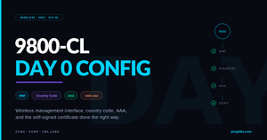
The 9800-CL is the only heavy VM you need; IOL XE images keep the rest of the lab almost free. An external connector in bridge mode is the trick that lets a real AP join a virtual controller, and it belongs at the access layer on its own VLAN. CML's simulated wireless nodes are Linux Wi-Fi, not CAPWAP APs - use them for client-side testing and use the physical AP for controller-side features. In Part 2 we bring the wired underlay up and walk the 9800-CL through its Day 0 configuration: wireless management interface, country code, and first GUI login. The full series index lives on the 9800 Wireless Labs page, and members can grab the importable topology from the lab files page.