
Data center networking is where the budget went. Campus refreshes are a line item; fabric builds are a programme, and the roles that pay best now assume you can talk about VTEPs, route targets and east-west traffic without a whiteboard. Along the way VXLAN with a BGP EVPN control plane stopped being the interesting new option and became the baseline. Design a data center network today without a spine-leaf fabric and EVPN, and you are expected to justify why.
This guide is the map. It covers what spine-leaf solves, the underlay and overlay split everything else hangs off, the reference addressing and EVPN route types you will keep looking up, the shortest configuration that produces a working L2VNI, the MTU problem that bites in production, and two traps this lab hit for real. Every output below is verbatim from a Nexus 9000v spine-leaf fabric running NX-OS 10.6(2) in Cisco Modeling Labs, so all of it is reproducible. Twelve deeper articles are indexed at the end.
What a spine-leaf fabric solves
The classic three-tier design (access, distribution, core) was built for a traffic pattern that no longer exists. It assumed north-south flows, so you aggregate upward and put the expensive routing at the top. Virtualisation, microservices and distributed storage broke that. The dominant flow is now east-west, and two servers three racks apart send traffic up to the distribution layer, possibly across a core, and back down. Path length depends on where the endpoints sit, so application performance depends on a rack allocation somebody made eighteen months ago.
The second problem was spanning tree. Layer 2 needs a loop-free topology and STP delivers it by turning links off, so you pay for bandwidth you are forbidden to use. Multi-chassis link aggregation pushed that out a bit (two uplinks bundled into one logical link, so STP sees no loop, the subject of Nexus port-channels and LACP), but you were still building a tree.
Spine-leaf is a two-tier Clos fabric and it changes the shape. Every leaf connects to every spine; no leaf connects to another leaf and no spine to another spine. The consequence is worth stating precisely: every leaf is exactly one spine hop from every other leaf. Not "usually", not "if they are in the same pod". Always. Latency is deterministic, capacity scales by adding spines, and nothing is blocked because every path is routed and ECMP uses all of them, as the spine-leaf OSPF underlay build shows.
How it works: underlay and overlay
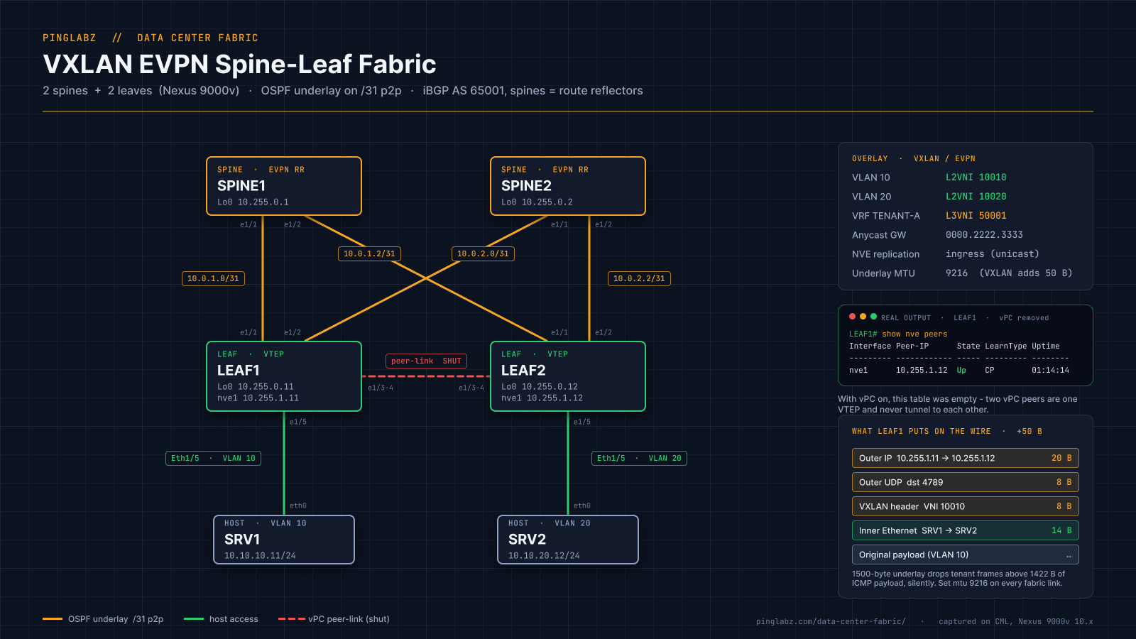
A fabric is two networks stacked on each other, and keeping them separate in your head is most of the battle.
The underlay is plain routed IP: point-to-point links, an IGP, loopbacks, ECMP. No VLANs cross it and nothing in it knows what a tenant is. The overlay is VXLAN, tenant Ethernet frames encapsulated in UDP between tunnel endpoints, with BGP EVPN distributing which MAC and IP addresses live behind which VTEP.
Here is the single most important idea in this entire cluster: the underlay only has to carry VTEP loopback reachability. The overlay does everything else.
That sounds too simple to be load-bearing, but it decides everything downstream. The underlay carries no tenant subnets, so it never grows when you add tenants. It knows nothing about VLANs, so a VLAN change is not a routing change. It has one job: get 10.255.1.11 to 10.255.1.12 over every available path, fast. The overlay takes on all the complexity that used to be smeared across the distribution layer, and carries it in BGP.
The reference cards
These are the two things you will keep scrolling back to. First, the topology and addressing used throughout this cluster. If the platform is unfamiliar, run the orientation pass in NX-OS fundamentals for your first console session first.
10.255.0.1, 10.255.0.2
10.255.0.11, 10.255.0.12
10.255.1.11, 10.255.1.12
10.255.1.100
10.0.1.1/31, 10.0.2.1/31
65001
10010, subnet 10.10.10.0/24
10020, subnet 10.10.20.0/24
50001
Two loopbacks per leaf, not one. Loopback0 is the control plane identity (OSPF router ID, BGP update source), Loopback1 is the VXLAN tunnel source. Separating them costs one /32 per switch and lets you share or renumber the VTEP address without disturbing a BGP session. On a vPC pair it is not optional.
Second, the EVPN route types. There are more than these, but a fabric without multihoming shows three.
Types 1 and 4 belong to EVPN multihoming, the standards-based replacement for vPC. This lab used vPC and single-homed servers, so it generated neither, and the EVPN route types walkthrough reads the three it did produce.
The core architectural concept: BGP EVPN as the control plane
Original VXLAN had no control plane. VTEPs learned remote MACs the way a switch always has, by flooding a frame everywhere and watching where the reply came from. Getting a broadcast to every VTEP meant multicast in the underlay, so layer 2 forwarding depended on a PIM design, flooding scaled with endpoint count, and answering "where is this MAC" meant checking every switch.
EVPN replaces remote data-plane learning with advertising. When a leaf learns a MAC on a local port (local learning is still classic data-plane learning) it originates a Type 2 route saying so, and every other leaf installs it. The resulting entry on the remote leaf is a control plane entry pointing at a VTEP address rather than a physical port. Nothing was flooded to produce it. Note what EVPN does not eliminate: ARP/ND still happens and BUM traffic still needs replication; discovery flooding is reduced and suppressed, not abolished.
What MP-BGP brings on top is everything the protocol already had. Route distinguishers keep overlapping tenant address space apart. Route targets control which VRF or VNI imports which routes, which is how multi-tenancy works without separate protocol instances. Extended communities carry the encapsulation type, the L3VNI label and the remote router MAC. Route reflection scales the peering mesh. And the troubleshooting commands and policy tools from your BGP fundamentals still apply, because EVPN is a new address family, not a new protocol.
The spines are the natural route reflectors: already adjacent to every leaf, carrying no tenant state, and reflecting through them turns a leaf-to-leaf full mesh into two sessions per leaf. One line matters more than it looks, retain route-target all, because a spine has no VRFs, imports no route targets, and without it discards the routes it exists to reflect. From the campus side, this is the same overlay idea as network virtualization with VXLAN and LISP with a different control plane.
Minimum viable fabric
The shortest path from four switches to a stretched VLAN: three blocks of configuration and five commands that prove it worked.
Start with the underlay. Every fabric link is a /31 with the point-to-point network type, and both loopbacks go into area 0. The point-to-point type is the line that matters: it removes the DR election, so adjacencies come up in seconds. The OSPF guides cover the mechanics.
feature ospf
router ospf UNDERLAY
  router-id 10.255.0.11
interface loopback0
  ip address 10.255.0.11/32
  ip router ospf UNDERLAY area 0.0.0.0
interface loopback1
  ip address 10.255.1.11/32
  ip router ospf UNDERLAY area 0.0.0.0
interface Ethernet1/1
  no switchport
  ip address 10.0.1.1/31
  ip ospf network point-to-point
  ip router ospf UNDERLAY area 0.0.0.0
  no shutdown
Then iBGP for the L2VPN EVPN address family, sourced from Loopback0, pointed at both spines. The leaf side is deliberately dull:
feature bgp
feature nv overlay
feature vn-segment-vlan-based
feature interface-vlan
nv overlay evpn
router bgp 65001
  router-id 10.255.0.11
  neighbor 10.255.0.1
    remote-as 65001
    update-source loopback0
    address-family l2vpn evpn
      send-community
      send-community extended
The spines mirror that with route-reflector-client under each neighbor and retain route-target all under the address family. Every protocol above needed a feature command first, the NX-OS habit that catches IOS XE engineers hardest and the first item in NX-OS versus IOS XE differences.
Now the overlay: map VLANs to VNIs, build the NVE interface with BGP host reachability and ingress replication, and declare the VNIs to EVPN so they derive an RD and route target automatically.
vlan 10
  name TENANT-A-WEB
  vn-segment 10010
interface nve1
  no shutdown
  host-reachability protocol bgp
  source-interface loopback1
  member vni 10010
    ingress-replication protocol bgp
evpn
  vni 10010 l2
    rd auto
    route-target import auto
    route-target export auto
Verification runs bottom up, underlay first, because nothing above it works if this is wrong:
show ip ospf neighbors

 OSPF Process ID UNDERLAY VRF default
 Total number of neighbors: 2
 Neighbor ID     Pri State            Up Time  Address         Interface
 10.255.0.1        1 FULL/ -          00:00:30 10.0.1.0        Eth1/1
 10.255.0.2        1 FULL/ -          00:00:29 10.0.2.0        Eth1/2
FULL/ - with no DR or BDR role is the point-to-point type doing its job, and both adjacencies came up in about thirty seconds. Next, the control plane:
show bgp l2vpn evpn summary

BGP summary information for VRF default, address family L2VPN EVPN
BGP router identifier 10.255.0.11, local AS number 65001
BGP table version is 4, L2VPN EVPN config peers 2, capable peers 2

Neighbor        V    AS    MsgRcvd    MsgSent   TblVer  InQ OutQ Up/Down  State/PfxRcd
10.255.0.1      4 65001          7          7        4    0    0 00:01:42 0
10.255.0.2      4 65001          7          7        4    0    0 00:01:31 0

Neighbor        T    AS Type-1     Type-2     Type-3     Type-4     Type-5     Type-6     Type-7     Type-8     Type-12
10.255.0.1      I 65001 0          0          0          0          0          0          0          0          0
10.255.0.2      I 65001 0          0          0          0          0          0          0          0          0
That second table, broken out per route type, is the fastest way to see what a peer is sending you. Then the tunnels and VNIs:
show nve peers

Interface Peer-IP                                 State LearnType Uptime   Router-Mac
--------- --------------------------------------  ----- --------- -------- -----------------
nve1      10.255.1.12                             Up    CP        01:14:14 n/a
show nve vni
Codes: CP - Control Plane DP - Data Plane
UC - Unconfigured SA - Suppress ARP
...
Interface VNI Multicast-group State Mode Type [BD/VRF] Flags
--------- -------- ----------------- ----- ---- ------------------ -----
nve1 10010 UnicastBGP Up CP L2 [10]
nve1 10020 UnicastBGP Up CP L2 [20]UnicastBGP in the Multicast-group column is how ingress replication announces itself; a PIM fabric holds a real group address there. CP means BGP populates forwarding. The full build is in the VXLAN L2VNI configuration walkthrough, the BUM decision behind ingress-replication protocol bgp in ingress replication versus PIM anycast RP, and routing between VNIs in the EVPN L3VNI and distributed anycast gateway build.
Finally, the only test that counts. Two servers in VLAN 10 on different leaves, with no layer 2 path between the leaves:
SRV1# ping -c 5 10.10.10.12

PING 10.10.10.12 (10.10.10.12) 56(84) bytes of data.
64 bytes from 10.10.10.12: icmp_seq=1 ttl=64 time=52.1 ms
64 bytes from 10.10.10.12: icmp_seq=2 ttl=64 time=15.2 ms
64 bytes from 10.10.10.12: icmp_seq=3 ttl=64 time=32.8 ms
64 bytes from 10.10.10.12: icmp_seq=4 ttl=64 time=20.3 ms
64 bytes from 10.10.10.12: icmp_seq=5 ttl=64 time=15.7 ms

--- 10.10.10.12 ping statistics ---
5 packets transmitted, 5 received, 0% packet loss, time 4005ms
rtt min/avg/max/mdev = 15.183/27.196/52.050/13.955 msttl=64, unchanged. The frames crossed two routed hops inside a VXLAN tunnel and the hosts have no idea. The whole promise of the overlay, in one field.
An operational concern: MTU
VXLAN adds 50 bytes to every frame when the outer frame is untagged Ethernet over an IPv4 underlay: 14 of outer Ethernet, 20 of outer IP, 8 of UDP and 8 of VXLAN header (an outer 802.1Q tag or an IPv6 underlay adds more), laid out field by field in the VXLAN encapsulation packet walk. Those bytes come out of somebody's budget, and unplanned they come out of your tenants'.
This lab was built with default 1500-byte underlay interfaces, the most common real-world VXLAN mistake, and it produced a precise boundary. Up to 1422 bytes of ICMP payload with the do-not-fragment bit set went through. One byte more vanished:
SRV1# ping -c 2 -M do -s 1422 10.10.20.12
1430 bytes from 10.10.20.12: icmp_seq=1 ttl=62 time=39.9 ms
1430 bytes from 10.10.20.12: icmp_seq=2 ttl=62 time=20.4 ms
2 packets transmitted, 2 received, 0% packet loss

SRV1# ping -c 2 -M do -s 1423 10.10.20.12
2 packets transmitted, 0 received, 100% packet loss, time 1026ms
The arithmetic lands on the nose: 1422 payload, plus 8 ICMP, 20 inner IP, 14 inner Ethernet, 8 VXLAN, 8 UDP and 20 outer IP, equals 1500. Tenants get 1450 bytes of inner IP MTU, and the failure is silent because the drop happens to the outer packet inside the fabric, so no ICMP unreachable reaches the host. The fix is mtu 9216 on every underlay-facing interface, spines and leaves both (9216 is the common Nexus jumbo ceiling; the real requirement is underlay MTU that covers tenant MTU plus your actual encapsulation overhead on your platform). Being straight about it: that command was applied to LEAF1 before the console session stalled, and the post-fix confirmation ping was not captured this session. The failure is measured, the remedy is standard practice rather than lab-proven.
Two traps this lab actually hit
Neither was planned, which is why they are worth more than the parts that went smoothly.
Trap one: two vPC peers are one VTEP, so they never peer with each other. With vPC configured and the anycast address 10.255.1.100 as a secondary on Loopback1, both leaves sourced VXLAN from the same address and advertised the same next hop. NX-OS says so, if you know where to look:
LEAF2# show nve interface nve1
 VPC Capability: VPC-VIP-Only [notified]
 Source-Interface: loopback1 (primary: 10.255.1.12, secondary: 10.255.1.100)
And the consequence, which is what actually sends people looking for a fault:
LEAF1# show nve peers
                    <empty>
Nothing is broken. A VTEP does not build a tunnel to itself, and two vPC peers sharing an anycast VTEP address are one logical VTEP to the rest of the fabric. Traffic between hosts on the two leaves crosses the peer-link as ordinary VLAN traffic, never VXLAN. Getting two distinct VTEPs for the remaining captures meant removing vPC and the secondary address. If vPC is new, start with the vPC build and health guide; if you are debugging one at 2am, the vPC peer-link and keepalive failure matrix is the faster read.
Trap two: the MTU black hole, covered above, earns a second mention for how it presents. Ping works, SSH works, then a file transfer stalls at 0 percent or a TLS handshake hangs after the client hello and nothing in any log says why. Both faults, plus LACP suspension and a vPC consistency failure, are dissected in the VXLAN EVPN troubleshooting guide.
The Full Cluster, in Reading Order
Twelve articles, all built on the same Nexus 9000v fabric. Read in this order from scratch, or jump to whichever section is currently on fire.
Start here: the NX-OS platform
- NX-OS vs IOS XE: what changes on your first Nexus - the six behaviors that catch IOS XE engineers out on day one.
- NX-OS fundamentals: your first thirty minutes on a Nexus - show version, show module, the feature model and CDP, before you configure anything.
Building the physical layer
- Nexus port-channels and LACP suspended members - the flags legend decoded, and why a suspended member is not a down one.
- vPC explained: build it and read its health - the four components of a vPC domain, show vpc field by field, and orphan ports.
The underlay
- Spine-leaf underlay with OSPF on Nexus - /31 links, point-to-point network type, loopback VTEP sources and ECMP across both spines.
The overlay control plane
- BGP EVPN route types 2, 3 and 5 with real output - route reflector config, retain route-target all, and how to read an EVPN prefix.
- Ingress replication vs PIM anycast RP for BUM traffic - how a fabric floods, and what you give up by not running multicast in the underlay.
The data plane
- VXLAN L2VNI configuration on Nexus, proven - the shortest working L2VNI and the anycast VTEP trap that emptied the peer table.
- A real VXLAN packet, header by header - a spine-to-leaf capture taken apart from raw hex, and a good companion to the packet analysis cluster.
- EVPN L3VNI and the distributed anycast gateway - the same gateway IP and MAC on every leaf, and the TTL that proves where routing happened.
When it breaks
- vPC failure modes: peer-link, keepalive and Type-1 - the failure matrix, with the Type-1 mismatch demonstrated and the rest explained rather than faked.
- VXLAN EVPN troubleshooting: what actually breaks - four faults hit in this lab, the output that found each, and an order for the next one.
FAQ
Is VXLAN EVPN overkill for a small data center?
Often, yes. Two racks, one tenant, no need to stretch a subnet and no growth plans: a pair of switches with VLANs and layer 2 switching plus a routed uplink serves you better. The honest triggers are multi-tenancy, workload mobility needing a subnet in two places, growth past one switch pair, and automation.
Do I need Nexus hardware to learn this?
No. Everything here came from Nexus 9000v switches in Cisco Modeling Labs, four nodes plus two container hosts on one server, and Arista cEOS, Cumulus and SONiC run EVPN in a lab too. What virtual boxes cannot give you is hardware behavior: TCAM carving, forwarding performance, ASIC-specific VNI scale limits, buffering under congestion. For the control plane, virtual is sufficient.
What is the difference between symmetric and asymmetric IRB?
Both route between VNIs. In asymmetric IRB the ingress leaf routes straight into the destination VNI, so every leaf needs every VLAN and VNI it might route toward, even ones with no local hosts. In symmetric IRB it routes into a shared transit L3VNI and the egress leaf routes out of it, so each leaf needs only the VLANs it serves plus the L3VNI. Symmetric is what Cisco implements and what scales; the tell here is a cross-subnet ping returning ttl=62, two decrements, one per leaf.
Does the underlay have to be OSPF?
No. IS-IS and eBGP are both common, and eBGP with a private AS per leaf is arguably the most widely deployed underlay in large fabrics. OSPF was chosen here because most engineers have it in muscle memory, and the underlay is not where you want to learn something new. What matters is the properties: fast convergence, ECMP across every spine, loopback /32 reachability.
How many VTEPs before ingress replication stops scaling?
The ingress VTEP sends one unicast copy of every BUM frame to every other VTEP in the VNI, so load is linear in VTEP count per VNI. Fine into the low tens, increasingly uncomfortable beyond. Mitigations usually arrive before the replacement does: ARP suppression removes the largest single source of broadcast, and keeping VNIs only on the leaves that need them shrinks every flood list. Underlay multicast with PIM scales better at high VTEP counts, at the cost of a multicast design. This lab used two VTEPs, which proves the mechanism and says nothing about the ceiling.
Is ACI dead now that Nexus One exists?
No, and the framing is an overstatement. Cisco's own position is that Nexus One encompasses and extends ACI rather than replacing it: the policy model, the hardware and existing deployments continue, with unified management reaching across both NX-OS and ACI estates. Cisco stopped selling two operating models and started selling one management layer over both, so an ACI investment is not stranded. If you are choosing now, the NX-OS plus VXLAN EVPN approach here is the standards-based path with the most transferable skills.
Key Takeaways
- Spine-leaf exists because traffic went east-west. Every leaf is one hop from every other, and nothing is blocked because every path is routed.
- The underlay only has to carry VTEP loopback reachability. Everything else is the overlay's job, and that separation keeps a fabric maintainable.
- EVPN is an address family, not a new protocol. Route distinguishers, route targets, extended communities and route reflection behave exactly as BGP taught you.
- Advertising beats flooding. A control plane MAC entry pointing at a remote VTEP came from a BGP update, not from a frame nobody knew what to do with.
- Plan MTU before you build. Fifty bytes of overhead on a 1500-byte underlay put this lab's boundary at 1422 bytes of payload, and the failure is silent.
- Two vPC peers sharing an anycast VTEP are one logical VTEP. An empty
show nve peersbetween them is correct, not a fault. - Verify bottom up: OSPF adjacencies, EVPN sessions, NVE peers, VNI state, host ping. Skipping a layer means finding the fault twice.