Configure Single Area OSPFv2 on Cisco Routers: Complete Lab Guide
Learn to configure and verify single-area OSPFv2 on Cisco routers with complete Router ID setup, network commands, and wildcard masks. Includes hands-on Cisco CML lab with full verification outputs and troubleshooting steps.

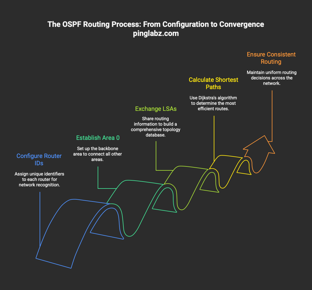
router ospf 1 to initiate the process. Set your Router ID with router-id 1.1.1.1 for topology stability, then enable OSPF on interfaces using network 192.168.1.0 0.0.0.255 area 0 with appropriate wildcard masks. Verify adjacencies with show ip ospf neighbor and check OSPF routes using show ip route. Proper area assignment and Router ID configuration guarantee successful neighbor formation and ideal path selection.Understanding OSPF Fundamentals
OSPF serves as your gateway to scalable, efficient routing within enterprise networks. You'll leverage this link-state protocol to manage routing information across complex topologies while maintaining ideal path selection through Dijkstra's algorithm.
Your OSPF implementation requires each router to maintain a unique Router ID (RID). You can manually configure this identifier or let the router automatically derive it from the highest loopback or active interface IP address.
Within your network's hierarchical structure, you'll typically deploy Area 0 as the backbone, connecting all other areas to facilitate route summarization.
OSPF routers exchange Link State Advertisements (LSAs) to construct a thorough topology database. This process enables each router to calculate the shortest path independently, ensuring consistent routing decisions across your autonomous system without routing loops or suboptimal paths.
Required Configuration Steps for Single-Area OSPFv2
Navigate to global configuration mode and initiate the OSPF routing process with the command router ospf [process-id], where you'll assign a locally significant process ID between 1 and 65535.
Next, configure a stable Router ID using router-id [ip-address] to prevent topology disruptions during network changes.
Enable OSPFv2 on specific interfaces with the network command:
network [ip-address] [wildcard-mask] area [area-id]- activates OSPF on matching interfaces- Wildcard masks determine which interfaces participate in the routing process
- All routers must share the same area designation for proper adjacency formation
For single-area deployments, you'll typically use Area 0 as the backbone. The network statement doesn't advertise networks; it identifies which interfaces run OSPF. Verify your wildcard mask accurately matches the intended interfaces to avoid configuration errors.
OSPF Router ID and Interface Selection
After establishing the OSPF process and network statements, you'll need to understand how routers select their Router ID and determine which interfaces participate in OSPF operations.
The OSPF Router ID uniquely identifies each router in the topology. Without explicit configuration, it's chosen from the highest loopback address or the highest IP on any active interface. You should explicitly configure it using router-id [x.x.x.x] to prevent recalculations during network changes.
For interface selection, you'll use the network command with wildcard masks. A mask of 0.0.0.0 matches exactly one address, while 0.0.255.255 matches addresses sharing the first two octets.
Alternatively, you can enable OSPF directly on interfaces using ip ospf [process-id] area [area-id], providing more precise control over which interfaces participate in OSPF operations.
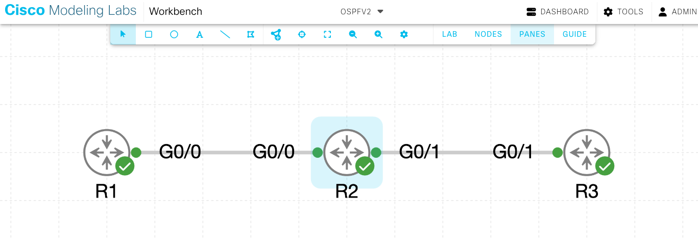
Step-by-Step OSPFv2 Configuration in Cisco CML (Area 0 Lab)
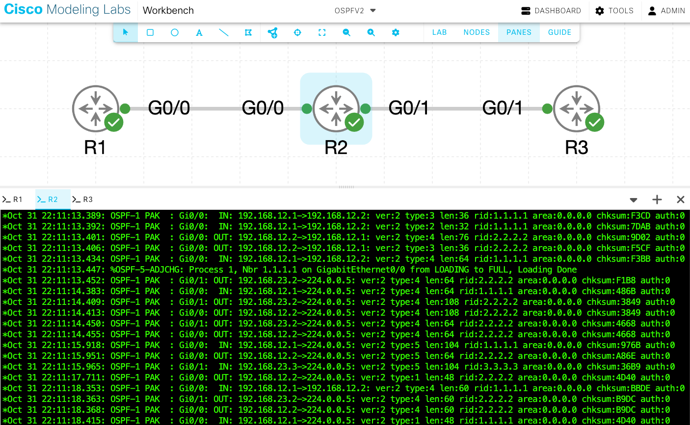
In this section, you'll configure and verify single-area OSPFv2 using Cisco Modeling Labs (CML). This hands-on example demonstrates the commands you've learned and ties them to real device outputs and verification steps.
Lab Topology Overview
For this example, we'll use three routers: R1, R2, and R3 all operating within Area 0.
IP Addressing Table
| Device | Interface | IP Address | Subnet | Area |
|---|---|---|---|---|
| R1 | Gig0/0 | 192.168.12.1 | /24 | 0 |
| R2 | Gig0/0 | 192.168.12.2 | /24 | 0 |
| R2 | Gig0/1 | 192.168.23.2 | /24 | 0 |
| R3 | Gig0/1 | 192.168.23.3 | /24 | 0 |
Router Configurations
R1 Configuration
R1(config)# interface GigabitEthernet0/0
R1(config-if)# ip address 192.168.12.1 255.255.255.0
R1(config-if)# no shutdown
!
R1(config)# router ospf 1
R1(config-router)# router-id 1.1.1.1
R1(config-router)# network 192.168.12.0 0.0.0.255 area 0
R2 Configuration
R2(config)# interface GigabitEthernet0/0
R2(config-if)# ip address 192.168.12.2 255.255.255.0
R2(config-if)# no shutdown
!
R2(config)# interface GigabitEthernet0/1
R2(config-if)# ip address 192.168.23.2 255.255.255.0
R2(config-if)# no shutdown
!
R2(config)# router ospf 1
R2(config-router)# router-id 2.2.2.2
R2(config-router)# network 192.168.12.0 0.0.0.255 area 0
R2(config-router)# network 192.168.23.0 0.0.0.255 area 0
R3 Configuration
R3(config)# interface GigabitEthernet0/1
R3(config-if)# ip address 192.168.23.3 255.255.255.0
R3(config-if)# no shutdown
!
R3(config)# router ospf 1
R3(config-router)# router-id 3.3.3.3
R3(config-router)# network 192.168.23.0 0.0.0.255 area 0
Explanation:
- Each router's interfaces are configured with their respective IP addresses before enabling OSPF
- R1 connects to R2 on the 192.168.12.0/24 network
- R2 connects to both R1 and R3, serving as the central router
- R3 connects to R2 on the 192.168.23.0/24 network
- After assigning Router IDs, the network commands enable OSPF on each interface under Area 0
Verification and Output
Once configuration is complete, use the following commands to confirm OSPF operation. Each command validates a specific part of your OSPF setup.
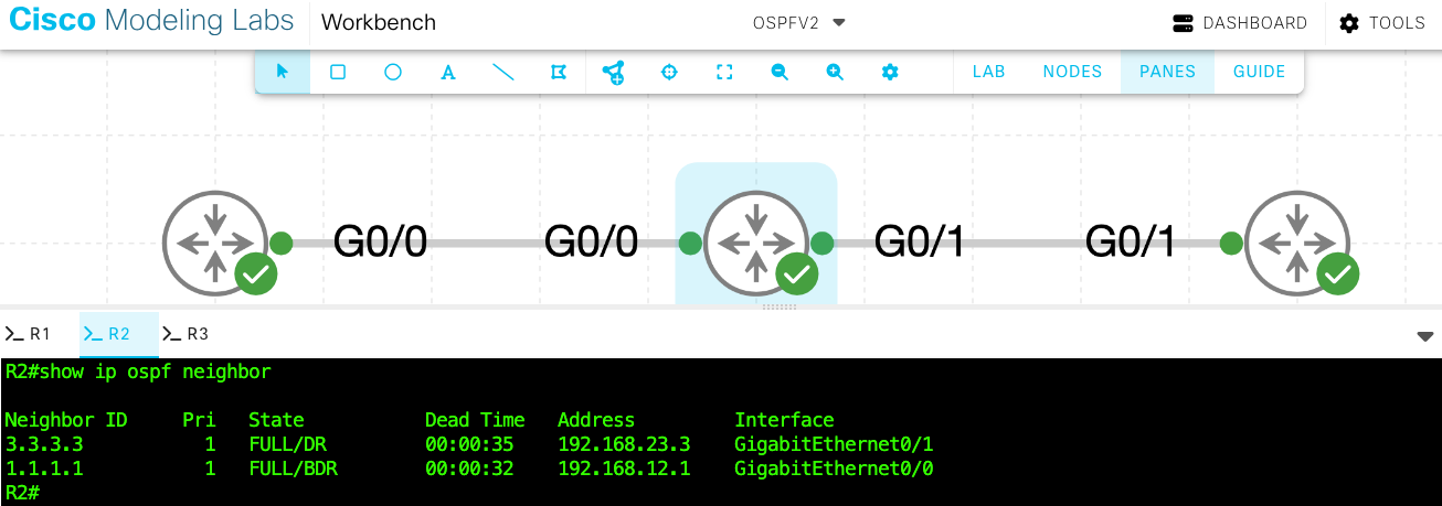
1. Verify Neighbor Adjacencies
This command ensures routers have successfully discovered one another and established full adjacencies.
R2# show ip ospf neighbor

Neighbor ID     Pri   State           Dead Time   Address         Interface
1.1.1.1           1   FULL/BDR        00:00:34    192.168.12.1    GigabitEthernet0/0
3.3.3.3           1   FULL/DR         00:00:37    192.168.23.3    GigabitEthernet0/1
R2 has full adjacencies with both R1 and R3, confirming proper OSPF neighbor relationships.
2. Verify OSPF Routes in the Routing Table
This confirms that routes learned via OSPF are being installed in the routing table.
R1# show ip route ospf
O    192.168.23.0/24 [110/20] via 192.168.12.2, 00:00:13, GigabitEthernet0/0
R1 successfully learns the 192.168.23.0/24 network through R2.
R3# show ip route ospf
O    192.168.12.0/24 [110/20] via 192.168.23.2, 00:00:19, GigabitEthernet0/1
R3 learns the 192.168.12.0/24 network from R2, confirming full route propagation.

3. Verify OSPF Process and Router ID
This displays process-level information such as Router ID, SPF statistics, and interface participation.
R2# show ip ospf

Routing Process "ospf 1" with ID 2.2.2.2
Supports only single TOS(TOS0) routes
SPF schedule delay 5 secs, Hold time between two SPFs 10 secs
Number of areas in this router is 1. 1 normal 0 stub 0 nssa
Area BACKBONE(0)
  Number of interfaces in this area is 2
  SPF algorithm last executed 00:00:03.456 ago
Confirms that R2 is running OSPF process 1 with Router ID 2.2.2.2 and two active interfaces in Area 0.
4. Inspect the Link-State Database (LSDB)
This verifies that all routers' LSAs have been received and synchronized.
R2# show ip ospf database

            OSPF Router with ID (2.2.2.2) (Process ID 1)

                Router Link States (Area 0)

Link ID         ADV Router      Age         Seq#       Checksum Link count
1.1.1.1         1.1.1.1         138         0x80000004 0x00C4B2 1
2.2.2.2         2.2.2.2         128         0x80000007 0x00E3F4 2
3.3.3.3         3.3.3.3         120         0x80000003 0x00A1C5 1
All routers' LSAs are present, indicating full database synchronization.
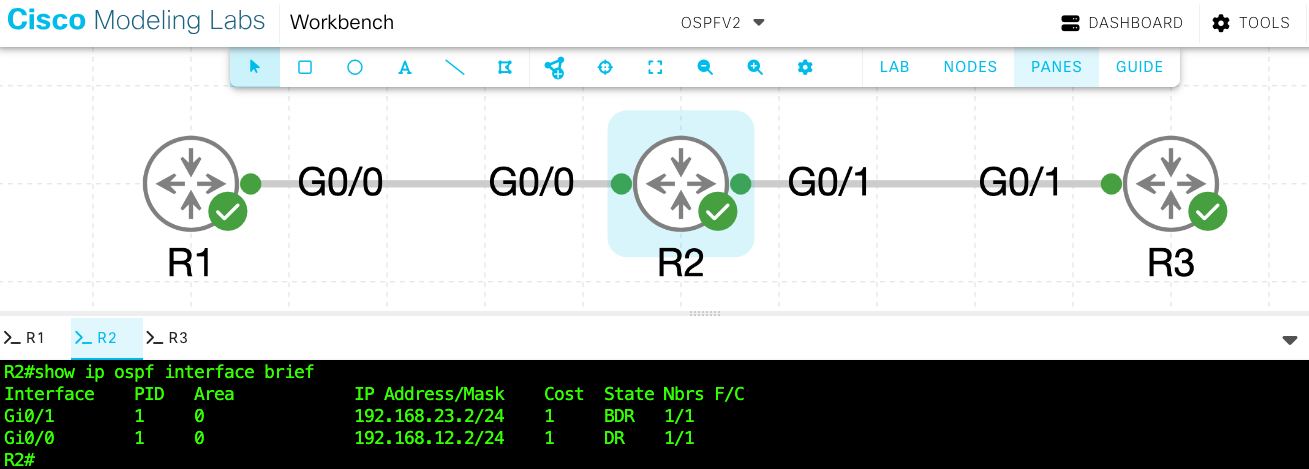
5. Verify OSPF Interfaces
Use this command to confirm which interfaces are active in OSPF and their neighbor relationships.
R2# show ip ospf interface brief

Interface    PID   Area   IP Address/Mask    Cost  State Nbrs F/C
Gi0/0        1     0      192.168.12.2/24   1     BDR   1/1
Gi0/1        1     0      192.168.23.2/24   1     DR    1/1
Both interfaces are active in Area 0, each maintaining one neighbor adjacency.
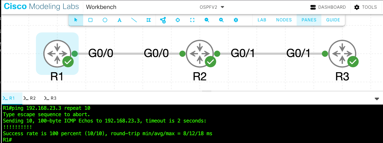
6. End-to-End Connectivity Test
A successful ping across the network confirms OSPF's routing functionality.
R1# ping 192.168.23.3
Type escape sequence to abort.
Sending 5, 100-byte ICMP Echos to 192.168.23.3, timeout is 2 seconds:
!!!!!
Success rate is 100 percent (5/5)
All packets were successful — verifying complete OSPF connectivity between routers.
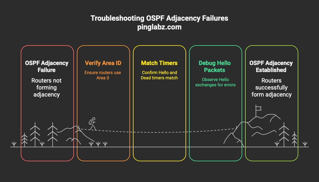
Troubleshooting Scenario Example
If R2 and R3 fail to form adjacency:
- Verify both routers use Area 0
- Confirm Hello and Dead timers match (
show ip ospf interface) - Use
debug ip ospf adjordebug ip ospf packetsto observe Hello exchanges - Ensure interfaces are not set to passive mode
Real-World Implementation Examples
When implementing OSPFv2 in production, topology designs can vary widely:
Hub-and-Spoke: The hub router uses multiple network statements for all spokes.
Dual-Router Redundancy: Both routers use matching area configurations but have unique Router IDs.
Full Mesh: Configure OSPF systematically across all links and verify each adjacency before moving forward.
Each design relies on the same OSPFv2 fundamentals—accurate area IDs, proper Router IDs, and verified adjacencies.
Frequently Asked Questions
How Does OSPFv2 Differ From OSPFv3?
OSPFv3 is designed for IPv6 and configured directly on interfaces using ipv6 ospf process-id area area-id. It doesn't rely on the network command and allows different link-local communication mechanisms.
What Are the Default Hello and Dead Timer Values?
The default hello timer is 10 seconds on broadcast and point-to-point links, with a 40-second dead timer. On NBMA networks, hello = 30 seconds and dead = 120 seconds.
Can OSPF Process IDs Differ Between Routers?
Yes. Process IDs are locally significant and don't need to match between neighbors.
How Many Routers Can Exist in a Single OSPF Area?
Cisco recommends a practical limit of 50 routers per area for manageability, though larger designs are technically possible.
Does OSPF Support Load Balancing?
Yes — OSPF automatically performs equal-cost multipath (ECMP) load balancing and installs up to four equal-cost routes by default.